Friday, February 10, 2012

A flashing LED "flash"

 Figure 1: Diagram of the circuit flash LED and components list.

I had a high brightness LEDs, such as the one you use in assembling EN5050 and I tried to design a flash using only a single integrated circuit CD4093 banal and two transistors, a PNP and NPN 2N3906 2N2222 . These transistors have nothing critical (I chose because I had them) and will be replaced by any other PNP and NPN equivalent.
As shown in the wiring diagram in Figure 1, I set up the first two NAND gates IC1/AIC1 / B to perform a reverse floor oscillator producing a square wave.
The output of gate IC1 / B is used to drive the base of the PNP transistor TR1 and the output of the third gate IC1 / C is used to drive the NPN transistor TR2.
The cathode K of the LED DL1 is connected to the collector of transistor TR2 and the anode A resistance R7. When the cursor turns trimmer R2 is varied the frequency of "flashes" (lightning).
The circuit operates at a voltage of about 12 to 15 V.

 Figure 2: Pinout top view of integrated circuit, transistors viewed below and the LED front view.

Component List
R1 ..... 2.2 M
R2 ..... 4.7 M trimmer
R3 ..... 2.2 k
R4 ..... 10 k
R5 ..... 2.2 k
R6 ..... 100
R7 ..... 100
TR1 .... PNP 2N3906
TR2 .... NPN 2N2222
IC1 .... CD4093
DL1 .... High Brightness LED
S1 ..... switch


Editor's Note
Because the circuit CD4093 has four doors, to avoid self-oscillation, it is better to connect the two ground unused inputs (pins 12-13 of IC1 / D).
Read More...

Thursday, February 9, 2012

Reduce the voltage supply 230 VAC to a DC voltage transformerless

 Figure 1: Diagram of the circuit without power transformer and component list.

Here's a good time that I manage to get the low voltage I need for my movies directly from the 230 V without using a transformer component heavy, bulky and expensive ... at least for my scholarship student IUT!
I replace the transformer reducing voltage by the capacitive reactance phenomenon: you know that when AC voltage is applied to a capacitor in series, it offers resistance to current flow (the reactor).
This resistance value R (in ohms) is based on the capacity C (uF) and the frequency F of the AC voltage (Hz), using the formula:

R = 159 000 (F x C)

In my circuit I built two capacitors of 1 uF 250 V series, making a total capacity of 0.5 uF; with the mains frequency 50 Hz, the resistive value of these capacitors will be:

159 000: (50 x 0.5) = 6360 ohms or 6.36 k.

I put two capacitors in series of 250 VDC operating voltage, which divides the two but double capacity by the voltage (that is to say continuous use without problems) and is therefore at 500 VDC.
Also in series with the voltage of 230 V, I added a resistor of 56 ohms 1 / 2 W as protection for the entire circuit.
I go out in a 1 W zener with a rated voltage is slightly higher than the voltage that I would get: for 12 V I choose a zener of 15-16 V to avoid that in the absence of load voltage not skyrocketing. To obtain an output voltage of 9 V I would choose a 10 V zener
I'm sure this little montage of interest to other electronics enthusiasts like me.

Component List
R1 ..... 56 1 / 2 W
C1 ..... 1 uF 250 V polyester
C2 ..... 1 uF 250 V polyester
C3 ..... 220 uF electrolytic 25-33 V
DZ1 .... Zener 1 W (see text)
RS1 .... 250 V rectifier


Editor's Note
fails to mention that this power is directly connected to a power of 230 V, if someone touches any part of the circuit when it is turned on, he will receive an electric shock can be fatal.
You should know also that it will not be obtained in this way a current exceeding 15 to 20 mA.
The reader may realize that a perforated plate mounting tape or pelletized, and may also practice drawing a real circuit board (it's very easy method to see the film Blue in Issue 26 of ELM or alternatively ask our advertisers).
Écouter
Lire phonétiquementDictionnaire - Afficher le dictionnaire
Read More...

Wednesday, February 8, 2012

Tester quartz up to 1 MHz

 Figure 1: Diagram of quartz tester whose core is less than 1 MHz.

You need to use this tester, a digital frequency meter (ELM has published many of which most are still available).

When I tried to test quartz of 500,000 Hz or 100,000 Hz with a tester trade, I could not get them to oscillate and at first I thought they were defective: I happily do not throw them because I tend to just keep everything! Indeed, when I reinsert in the telephone from which I had taken, the devices worked normally! I have therefore concluded that all testers quartz trade can not test the quartz oscillating at a frequency below 1 MHz. So I tried to make a can "descend" at frequencies up to 50 kHz.
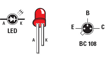
As shown in the wiring diagram in Figure 1, the circuit uses two NPN transistors of the most common (you can also substitute other types, provided that they are of NPN), BC108, BC107, etc.. These two transistors are connected in order oscillators to oscillate the quartz to test the available frequency on the two collectors of TR1 and TR2.
For the oscillation frequency of the quartz test, you need a digital frequency: connect it to the BNC tester, which in turn is connected to the collector of TR1 via a resistor R4 1 k and a capacitor C2 100 pF. The frequency reading on the digital frequency is that which the quartz oscillates tested.
The circuit can be powered by a battery of 4.5 V square or a 9 V

 Figure 2: Pin LED front view and the NPN transistor from below.

Component List
R1 ...... 390
R2 ...... 100 K
R3 ...... 3.9 k
R4 ...... 1 k
R5 ...... 3.9 k
R6 ...... 3.9 k
R7 ...... 100 K
R8 ...... 3.9 k
C1 ...... 10 nF ceramic
C2 ...... 100 pF ceramic
C3 ...... 100 pF ceramic
C4 ...... 100-110 pF capacitor adjustable
C5 ...... 10 uF electrolytic
DS1 ..... 1N914
DS2 ..... 1N914
TR1 ..... NPN BC108
TR2 ..... NPN BC108
S1 ...... switch
XTAL .... quartz test


Editor's Note
We can install this excellent tester for quartz at frequencies below 1 MHz in a small metal box with the front or the back of a BNC output and on top of several formats quartz packages connected in parallel; Also make sure that we can reach the axis of the small adjustable capacitor C4 from the outside with a small plastic screwdriver (known as "HF"). This adjustable capacitor is used to start a swing a little stubborn.
S1 and DL1 are mounted on the front and the battery will fit inside the box.
Read More...

Tuesday, February 7, 2012

Automatism Photoresistive

 Figure 1: Diagram of the automation photoresistor.

thyristor feeds a dc voltage from 12 to 14 V.


I realized this automation to solve a problem that I faced, but I send it because I think it will serve many readers ELM.
Indeed, when I got in my garage at night with headlights turned on and I put out ... I found myself in the dark! Then began the perilous march blindly, arms stretched forward to reach the light switch: so long as my son has not left his tricycle in the middle of the trail!
With this circuit I have completely solved the problem because when I come home at night and it is night, I enter the garage with the headlights turned on, the light of these flood the sensitive surface FTR1 a photoresistor whose resistance decreases as a result of the illumination, allowing the shipment to the gate of thyristor TH1 to a voltage more than enough to do drive.
Once it starts to conduct, its anode is traversed by a current that activates relay RL1 which contacts feed a small bulb 230 V from March to May W (enough that illuminates the garage). Of course, when I cut the headlights, this little lamp is lit: I can then exit the vehicle and reach the main light switch without a hitch.
But the emergency bulb will she have to stay on? How to disable the relay? Well I just open the switch S1 (see Figure 1), which provides the 12 V circuit, then to close it that lights the LED DL1 using night-so that the circuit is powered up next use.
For any adjustment, you must turn on the headlights and slowly turn the cursor trimmer R1 to the photoresist so as to activate the relay, then turn off the lights of the vehicle, opening the switch S1 and then slowly turn the cursor R1 in reverse until extinction of the small bulb.
When it resumes the starting position S1, DL1 lights and not the small bulb: it will remain off until the photocell is illuminated by the headlights. It goes without saying that said photoresistor will be placed at the height of the vehicle headlights.
For my setup, I used a plastic BT152.800 thyristor, which cost me a euro fifty, but a metal model of any type will go equally well, provided that it demands a control current between 10 and 20 mA.

 Figure 2: Pinout thyristor and viewed from the front LED.

Component List
R1 ..... 22 k trimmer
R2 ..... 1 k
C1 ...... 22 uF electrolytic
C2 ...... 100 nF polyester
DS1 .... 1N4004 or 1N4007
DL1 .... LED
TH1 .... thyristor BT152.800
FTR1 ... photoresistor
RL1 .... 1 contact relay 12 V
S1 ..... switch


Editor's Note
In another type of application, if you need to order a load more powerful, you can mount a power relay RL1 below: At this time the contacts of RL1 control the feeding of the relay winding power output contacts which control the load.
Read More...

Monday, February 6, 2012

A three-tone ringer


I have a small company whose premises consist of two long wings of the building and everything is served by three entries spread: Well now, thanks to the editing that I'll offer you, the employee assigned to receive recognition "to ear "in which someone has just three entries sound, in fact, the bell button of each entry determines" its "own sound.
I designed the circuit has definitely solved the problem that arose before and that everyone can easily guess: each entry is associated with a different sound and we know where the person presents.
To achieve this I used a unijunction transistor 2N2160 in metal case that I paid just one euro in a retail electronics. The wiring diagram of Figure 1 shows that by pressing one of three buttons P1-P2-P3 is connected to the emitter of transistor UJT1 resistance of different value each time R1-R2-R3, with the ability the capacitor C1 of 220 nF each determines a different frequency. Three notes 150-480-1 500 Hz
If you want to make the higher notes, just reduce the ability of C1 and if you want to change the frequency of a single note, change the value of the corresponding resistor connected to the transmitter.
Initially, to find a note that suited me, I replaced the three by three resistors 22 k trimmers ... and I turned their axes until you find the "good" rating for each of the three "channels". Nothing prevents them then leave.
Now we must decide what final stage up to drive a small speaker. For my part I took your edit EN1306: This small amplifier integrated circuit (see Figure 3) gives a power of 1 W and can also take the EN1307 provides 5 W (see Figure 4). The volume pot of EN1306 R1 works by making the mass a more or less of the resistor connected to pin 4 of integrated circuit of Figure 3 or pin 5 of that of Figure 4. Both models of amplifiers feeding into 12 V.

 Figure 1: Electrical generator circuit notes.

Exits ABC are right to connect to the inputs of the amplifier ABC chose, that of Figure 3 (1 W) or that of Figure 4 (5 W).

Component List
R1 ..... 18 k
R2 ..... 5.6 k
R3 ..... 1.8 k
R4 ..... 330
C1 ...... 220 nF polyester
UJT1 .. 2N2160 unijunction
P1 ...... push
P2 ...... push
P3 ...... push


 Figure 2: Assignment of the integrated circuit TDA7052 / B seen from above, the transistor UJT 2N2160 (he has two bases B1 and B2 and no collector) from below and the integrated circuit TDA7056 / B front view.
 Figure 3: Diagram of the amplifier EN1306.

This amplifier provides a power of 1 W, it is available with its printed circuit board.


Component List
R1 ..... 1 million pot. flax.
C1 ...... 470 nF polyester
C2 ...... 100 nF polyester
C3 ...... 220 uF electrolytic
C4 ...... 100 nF polyester
IC1 ..... TDA7052 / B
HP ..... Speaker 8 ohm

 Figure 4: Diagram of the amplifier EN1307.

This amplifier provides a power of 5 W, it is available with its printed circuit board.


Component List
R1 ..... 1 million pot. flax.
C1 ..... 470 nF polyester
C2 ..... 100 nF polyester
C3 ..... 220 uF electrolytic
C4 ..... 100 nF polyester
IC1 .... TDA7056 / B
HP ..... Speaker 8 ohm


Editor's Note
We have nothing to add other than (for newbies) that the generator circuit of notes in Figure 1 receives power from one of the two amplifiers of Figures 3 or 4 (who themselves need an external power 12 VDC 1 A
The reader can perform the assembly of Figure 1 for a perforated plate pelletized or bands.
Read More...

Sunday, February 5, 2012

A seven segment display digital giant

This module display seven segment series giant to do everything you can (in combination with other platinum and a control) to set up tables illuminated digital display. Each connects in parallel with others and the latter receives a "Terminator" (plug) formed of a resistor. It can be controlled by a computer or simply by a microcontroller: it is this last possibility that has been used in the assembly following ET610 you can read right after this article.

 Figure 1: Diagram of the giant digital display.

This module display seven segment giant is used alone or, more likely, in combination with one, three or four others (see article in this issue ET610 ELM).
You can fly it with a computer (RS232 serial port) or a microcontroller (solution adopted by Article ET610): in all cases more modules are mounted in cascade and not to mention the resistance cap for the last chain.
The practical realization of this double-sided platinum seven segment digital display will not be a problem even for a beginner.
You fund it or the seven-segment displays with a voltage of 12 V is applied to V + and GND points. Include a consumption of 100 mA for each display and allow a good margin of safety. You should not forget to configure the address of each of the displays you need, the procedure is very simple.
You will have such a power supply that provides at least 1A at 12V DC for 6 displays.
The deck of each display module can take place inside the plastic casing of red (available in different sizes depending on what you want to achieve, see section ET610): advertisers will not fail to advise you on choosing a solution.

 Figure 2: Photograph of a prototype of the plate of the giant digital display.

Note the jumper JP1 used to give his own address to the display module: to do, feed this display after closing the jumper (SK Address Change) between T1 and IC1, then the display shows a digit scrolling; when the number corresponding to the desired address is displayed, remove the jumper and the address is assigned. Repeat for the other or any other displays.
232 points, as the points + V GND are cascaded (parallel) when we use multiple modules, or for driving with a computer or to control them with a microcontroller (such as the application ET610, see section below). In the case of several modules in cascade, do not forget to get on the last of the chain stopper resistive (resistance) R2 of 560 ohms.


giant digital display. EV8063
R1 ..... 560 Ω
R2 ..... 560 Ω
R3 ..... 10 kW
R4 ..... 1 kΩ
R5 ..... 100 Ω
R6 ..... 100 Ω
R7 ..... 100 Ω
R8 ..... 100 Ω
R9 ..... 100 Ω
R10 .... 100 Ω
R11 .... 100 Ω
R12 .... 100 Ω
R13 .... 100 Ω
C1 ..... 100 nF multilayer
C2 ..... 100 nF multilayer
C3 ..... 100 nF multilayer
C4 ..... 100 uF 25 V electrolytic
C5 ..... 100 uF 25 V electrolytic
D1 ..... 1N4007
ZD1 .... Zener 5.1 V 400 mW
ZD2 .... Zener 5.1 V 400 mW
Zd3 .... Zener 4.3 V 400 mW
AF1 .... seven segment display 44 x 70 mm Common Anode
T1 ..... BC547
IC1 ..... PIC16F630-EV8063 already programmed in the factory
VR1 .... 7809

Others:
1 2 x 7 support
A 6 mm bolt 3MA
1 rider 2.54 mm pitch
2 strips 2.54 mm pitch male
SIL 1 female connector 2.54 mm pitch

Note: All resistors are tons of neighborhoods W.
Read More...

Saturday, February 4, 2012

An RX for HF anti burglar of pocket

It's a small UHF radio receiver that receives the signal from the transmitter (for the latter see previous story) as they are close, everything is fine and the receiver remains silent, but if they are away, the buzzer associated with it starts screaming and warns us of the event!

 Figure 1: Diagram of RX for locks pickpocketing.

This receiver is for use with the small transmitter UHF 433.92 MHz to produce a system lock or anti-pocketing distance HF.
The construction of the RX will not be a problem if more than the care you bring to your work.
It's also a montage dedicated to beginners. Figure 1 shows a diagram and list of components will allow everyone to get it right.
All necessary components are again available from certain advertisers of the magazine.

 Figure 2: Photograph of a prototype of platinum anti-theft system for the RX-pocketing.

hybrid receiver module can be directly soldered into holes in the PCB and then inserted into a socket strip. Integrated circuits are mounted on stands. The 12V battery is determined by its electrodes welded to it. The UHF antenna is a simple piece of insulated copper wire 17 cm. The small dimensions of the RX you will at his discretion.


Iist ET587RX
R1 ...... 680 Ω
R2 ...... 390 kΩ
R3 ...... 220 kΩ
R4 ...... 2.2 MΩ
C1 ...... 22 uF 35 V electrolytic
C2 ...... 330 nF 63 V polyester
C3 ...... 10 nF 250 V polyester
C4 ...... 10 uF 100 V electrolytic
D1 ...... 1N4148
DZ1 ..... Zener 5.1 V 1 / 2 W
LD1 ..... LED 3 mm red
BZ1 ..... with electronic buzzer
U1 ...... RF290-433
U2 ...... MC145028
U3 ...... 4093
SW1 ..... slide switch

Miscellaneous:
1 support 2 x 8-pin
1 support 2 x 7-pin
3 2-pin jumpers
1 row female / male 15 holes / pins for the hybrid module
1 pair of clips for 12V battery for printed circuit
Read More...

Most visited posts this week