 Figure 1: Diagram of quartz tester whose core is less than 1 MHz.
 You need to use this tester, a digital frequency meter (ELM has published many of which most are still available).
When I tried to test quartz of 500,000 Hz or 100,000 Hz with a tester trade, I could not get them to oscillate and at first I thought they were defective: I happily do not throw them because I tend to just keep everything! Indeed, when I reinsert in the telephone from which I had taken, the devices worked normally! I have therefore concluded that all testers quartz trade can not test the quartz oscillating at a frequency below 1 MHz. So I tried to make a can "descend" at frequencies up to 50 kHz.
As shown in the wiring diagram in Figure 1, the circuit uses two NPN transistors of the most common (you can also substitute other types, provided that they are of NPN), BC108, BC107, etc.. These two transistors are connected in order oscillators to oscillate the quartz to test the available frequency on the two collectors of TR1 and TR2.
For the oscillation frequency of the quartz test, you need a digital frequency: connect it to the BNC tester, which in turn is connected to the collector of TR1 via a resistor R4 1 k and a capacitor C2 100 pF. The frequency reading on the digital frequency is that which the quartz oscillates tested.
The circuit can be powered by a battery of 4.5 V square or a 9 V
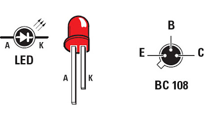
 Figure 2: Pin LED front view and the NPN transistor from below.
 Component List
R1 ...... 390
R2 ...... 100 K
R3 ...... 3.9 k
R4 ...... 1 k
R5 ...... 3.9 k
R6 ...... 3.9 k
R7 ...... 100 K
R8 ...... 3.9 k
C1 ...... 10 nF ceramic
C2 ...... 100 pF ceramic
C3 ...... 100 pF ceramic
C4 ...... 100-110 pF capacitor adjustable
C5 ...... 10 uF electrolytic
DS1 ..... 1N914
DS2 ..... 1N914
TR1 ..... NPN BC108
TR2 ..... NPN BC108
S1 ...... switch
XTAL .... quartz test
Editor's Note
We can install this excellent tester for quartz at frequencies below 1 MHz in a small metal box with the front or the back of a BNC output and on top of several formats quartz packages connected in parallel; Also make sure that we can reach the axis of the small adjustable capacitor C4 from the outside with a small plastic screwdriver (known as "HF"). This adjustable capacitor is used to start a swing a little stubborn.
S1 and DL1 are mounted on the front and the battery will fit inside the box.


No comments:
Post a Comment