
I) Presentation :
The problem of signal transmission by audio frequency electromagnetic wave
led in recent years of practical arrangements with a number
disadvantages.
First, we often work at a very low frequency (of the order of hundreds of
kHz) in a band (medium wave or long wave) where emissions are not
allowed.
In addition to these low frequency antennas, to be effective, necessarily
very long since the antenna size must correspond to a quarter or demilongueur
wave. It then comes to situations where the scope of the system is hardly more
important than total length of transmission antennas and reception. This is
embarrassing when we have before us an amateur student who discussed the previous night
with a friend in New Zealand ...
It can also remove the antennas and to generate and capture the electromagnetic wave by a
coil tuned to the frequency. This is the solution adopted in our
receptors and LW. In this case it is necessary to issue a strong current in the coil
emission if the scope is still quite low.
The solution to this problem is simple: just go up in frequency. Enough
able to use antennas bit bulky, but not too much to remain compatible with
usual equipment of our laboratories for Physics.
For this reason we developed this model consists of a small
transmitter and a receiver that has the following characteristics:
• Frequency of work in the CB around 27 MHz where the issue of low power
is free
· Antenna transmitting and receiving readily available and of reasonable length - the
quarter-wave wire is 2.5 m but there are granted spiral antennas of 25 cm
· Emission standard amplitude modulation, the modulating signal from either a
low-frequency generator, or from any source (Walkman, etc ...)
RANGES free space greater than 100m, which is more than enough to be received
bottom of the lab, if the issuer is on the teacher's desk
· The possibility to work several models on the same frequency. In this case a
single transmitter is working and students study the receptor
· It can also work with several sets transceiver by setting each
a different pulse frequency
II) Structure of the Issuer:
It is built around an AD835 analog multiplier which can operate up to 250
MHz and is perfect for our application. It has two inputs X and Y and a
Input summation Z and realizes the function:
e (t) = Z + x.y
If we apply the modulating signal s (t) in X and the carrier eo (t) = Ecos (wet) in both Y and Z,
it will output:
e (t) = s (t). Ecos (wet) + Ecos (wet) = E (1 + s (t)) cos (wet)
In the case where the signal is low-frequency sine wave: s (t) = acos (Wt), we obtain:
e (t) = E (1 + acos (Wt)) cos (wet)
which is an amplitude modulated signal, a modulation depth of m = 1 is obtained
for low-frequency signal amplitude a = 1V.

Figure 1 : structure of the issuer
In addition to the multiplier, the model includes an oscillator with two transistors that provides
carrier frequency fe of quartz. This oscillator requires no adjustment and functioning
when powering up.
To make this operational transmitter, it suffices to equip it with an antenna (rod
metal 10 to 30cm in length or at least better flexible antenna tuned for CB 27
MHz) and apply to the input signal modulating an amplitude of less than 1V if we want
avoid overmodulation.
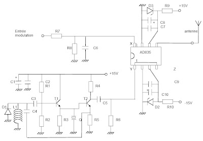
The complete diagram of the transmitter is as follows:

Figure 2 : diagram of the transmitter
Resistors :
R1 = 68 kW R2 = 100 kW R3 = 10 kW R4 = 1 kW R5 = 470 W
R6 = 330 W R7 = 100 W R8 = 4,7 kW R9 = 330 W R10 = 330 W
Capacitors :
C1 = C8 = C10 = 22 mF C2 = C7 = C9 = 100 nF
C3 = C5 = C6 = 3,3 nF C4 = 220 pF
Other components :
L1 = 470 nH
D1 = 1N4148 D2 = D3 = Zener diode 5,1V
T1 = T2 = 2N 4401 CI : multiplier AD 835 from Analog Devices
Q = quartz emission corresponds to a frequency fe of the 40 channels from the CB
III) Receptor structure :
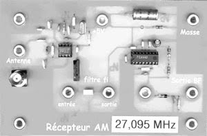
This is obviously a receiver to change frequency. The signal received by the antenna
is multiplied (NE602 circuit) by a sinusoidal signal whose frequency f is shifted by
compared to the emission frequency of fi = 455kHz:
for = fe - 455kHz
We obtain an output signal at the sum frequency fe + fo, not exploited in the model, and
the difference frequency fe = fi-fo.
This signal at the frequency f is selected using a selective filter centered on the ceramic
value of standard intermediate frequency 455 kHz.
The emission at the frequency we are interested in himself has been transposed to 455 kHz and cross
the intermediate frequency filter with minimal attenuation.
Emissions at frequencies near (CB enthusiasts, other models etc ...) will be
transposed above or below 455 kHz and therefore significantly reduced.
The filter output if the carrier level is highly variable depending on the type of antenna used
and the distance between the transmitter and receiver. It should therefore amplify the signal coming out of the filter
without clipping, which would be tragic for our modulation.
To attack the peak detector with a substantially constant level, we use
an amplifier with automatic gain control circuit (TCA 440).
The demodulator is a simple peak detector assembly well known.

Figure 3: receptor structure
It is clear that at present a single integrated circuit enables a complete receiver.
But our concern was to separate the different functions encountered in a
receiver, and to place the measurement points at locations that are not always
available in receivers to a single circuit.
It is also for didactic reasons we wanted to have a peak detector
separate from the intermediate frequency amplifier.
The diagram of the receiver is:

Figure 4 : complete diagram of the receiver
Resistors :
R1 = 10 kW R2 = 47 kW R3 = 22 kW
Capacitors :
C1 = C3 = C6 = 3,3 nF C2 = 68 pF C5 = 100 pF
C4 = C8 = C9 = C10 = C11 = C12 = 100 nF C7 = 47 pF C13 = 1 mF
C14 = 1,2 nF C15 = 1 nF
Other ingredients:
D1 = D2 = peak germanium diode OA 95 or equivalent
L1 = L2 = 470 nH L3 = 100mH
DO = CI1 CI2 NE612 = 602 or 440 TCA
F = 455 kHz ceramic filter
Q = quartz receiving frequency f = fe - 455 kHz
or for = fe + 455 kHz
IV) Some practical tips :
If you work at a small distance (less than 3m) does not put the antenna on the transmitter
to avoid saturation of the input stage of the receiver: the demodulated signal will be better.
For a distance of several meters, an antenna made of a conductor (copper,
brass, piano wire ...) to ten cm mounted on a banana plug is fine.
Both antennas supplied with flexible models are needed only for
transceiver distances greater than 10 m.
Always feed the two models by two different power supplies, otherwise the password HF
a model to the other by the son of power and not by the antennas, which is not
really the goal
To plot the frequency response of the ceramic filter selective to 455 kHz,
necessary to remove the blue jumper, attacking the filter by a GBF and increase the output signal of the filter
the voltmeter or oscilloscope equipped with conventional lighting (no cord with BNC
parasitic capacitance changes the shape of the gain curve)
To plot the curve vs = f (er) fi AGC amplifier, the filter attack by GBF and
raise the output signal of the amplifier, before the peak detector.
Important Notes :
For the issuer, if the 27 MHz oscillator does not start, add a capacitor of 47 pF
parallel with L1 and D1
At the receiver, to improve the operation of the NE602, add resistance
2.2 kW between lug 5 of this circuit and the +5 V supply (this resistance was not
provided on the original artwork).

No comments:
Post a Comment